
Home / Custom & OEM
OEM / ODM program
Your requirements. One engineering path.
Battery packs, chargers and circuit design. Work with our in-house engineering team from first requirements to samples, testing and production.
01Spec brief builder
Build a spec brief for our engineers
Fill in what you know. Leave the rest blank or choose "Not sure". The spec sheet on the right fills in as you type, and you can email or copy it.
02Project path
Six stages, and what each side brings
The same path for battery packs, chargers and PCB-only projects. Small quantities are accepted at every stage.
- 01
Requirements
Tell us what the pack or charger has to power and where it has to fit.
We do
- Our in-house engineering team reviews your device and how it is used.
- We list what is needed to start the design and help you fill the gaps.
- We tell you which certification documents exist for certified models, on request.
You provide
- The device or application
- Voltage and capacity, or the runtime you need
- Size limits and the connector or contacts
- Whether you also need a charger
- Quantity stage: prototype, pilot run or production
- Unknown values are fine. We work them out with you.
- 02
Circuit design
We design the battery PCB (protection circuit) and the charger PCB in-house.
We do
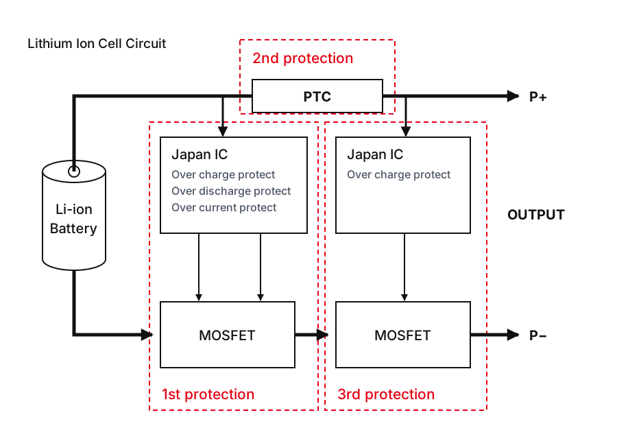
- Battery PCB with three levels of protection: Japanese protection IC + MOSFET (1st and 3rd), PTC (2nd).
- Protection IC for over-charge, over-discharge and over-current.
- Fuel gauge (gas gauge) for smart batteries when your device needs it.
- Charger PCB designed to match your pack.
You provide
- Charge and discharge needs of your device
- Connector pin-out or contact layout
- Whether the battery must report its charge level (fuel gauge)
- Standards your market requires
- 03
Prototype
We build prototype packs and chargers so you can check fit and function in your device.
We do
- Prototype packs and chargers built in our own production.
- Small quantities accepted, so samples and pilot runs are possible.
- Design changes made after your feedback, with quick, flexible production.
You provide
- Fit and function results from your device
- Changes you need before validation
- 04
Battery Lab validation
Our in-house Battery Lab has equipment for the UN 38.3 test items T1 to T8, plus an explosion-proof test chamber.
We do
- T1Altitude simulation
- T2Thermal
- T3Vibration
- T4Shock
- T5External short circuit
- T6Crush / impact
- T7Overcharge
- T8Forced discharge
You provide
- The markets you sell into
- The standards or documents your customers ask for
- 05
Production
Products are manufactured under ISO 9001, and every product carries a printed traceability code.
We do
- Incoming materials and cells are tested before production.
- Manufacturing under ISO 9001.
- A printed code on every product records who built it, which process step and the date code.
- Small-quantity and flexible production.
You provide
- Approved sample and final specification
- Order quantity and delivery schedule
- Label or marking requirements
- 06
QC report & shipping
Every battery pack is tested, and a QC test report ships with every shipment.
We do
- Every battery pack tested before packing.
- QC test report included in every shipment.
- Packed to SOP in export cartons.
- Express shipping to the US and Europe by UPS or FedEx.
You provide
- Ship-to address
- Preferred carrier: UPS or FedEx
03Circuit design
Battery PCB and charger PCB, designed in-house
We design the protection circuit inside the pack and the charger PCB that charges it.
Three levels of protection
Point to a level to find it on the drawing.
- 11st protectionProtection IC + MOSFET. A Japanese protection IC checks for over-charge, over-discharge and over-current, and controls a MOSFET on the P− line.
- 22nd protectionPTC. A PTC sits in series on the P+ output line as a separate, second level of protection.
- 33rd protectionSecond protection IC + MOSFET. A second Japanese protection IC adds its own over-charge protection, with its own MOSFET on the P− line.
Charger PCB
Designed together with the pack, for single-bay, dual-bay, 4-bay, 6-bay and multi-bay chargers. See charger types.
Smart batteries
Add a fuel gauge (gas gauge) when the battery has to report its charge level. See smart batteries.